Installation of a Rebel 660T x 24′ press brake
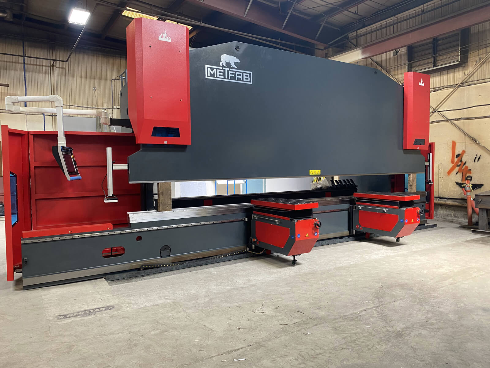
Our team is currently in Manitoba for a major installation this week: a Rebel 660T x 24′ press brake of a total weight of 150,000 lbs. Several days are necessary to assemble this massive press brake and to connect the hydraulic and electrical elements.
We decided to make a photo report to show you the massive work to do. Fortunately, we are there for you throughout this process, to deliver, install and train you on your press brake.
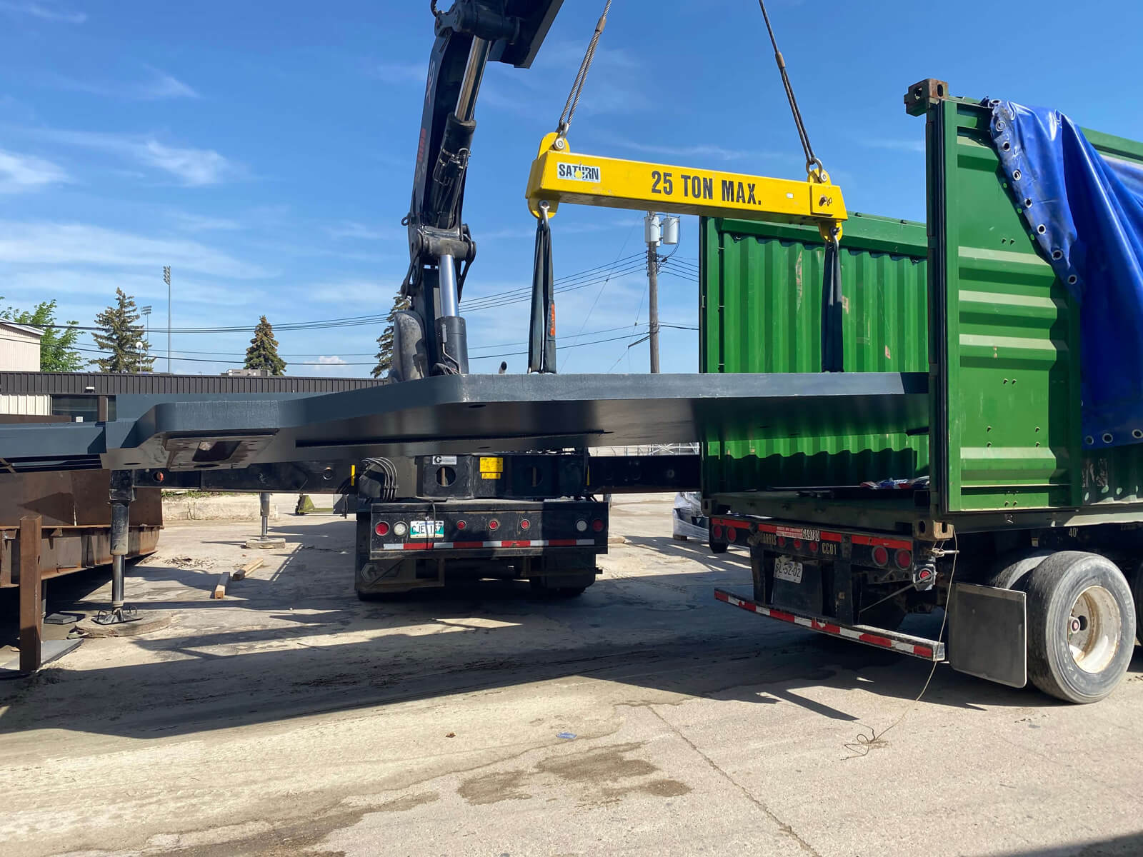
Step 1 – Unloading the press brake
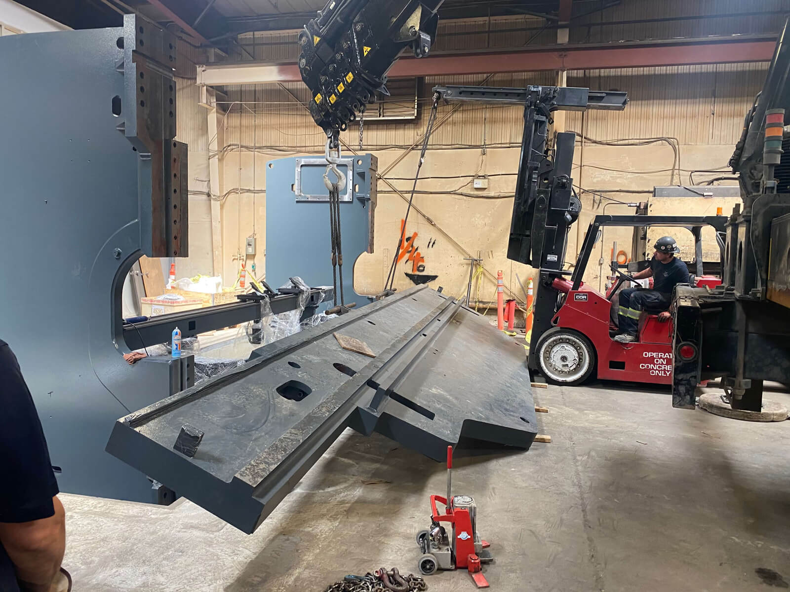
The press brake 660T is too massive to be carried in only one truck, we had to distribute the parts of the press brake in 3 containers of 40 feet each, in order to be able to deliver it in Manitoba, Canada. A whole team was called on the site to unload the machine with big cranes over 20 tons capacity.
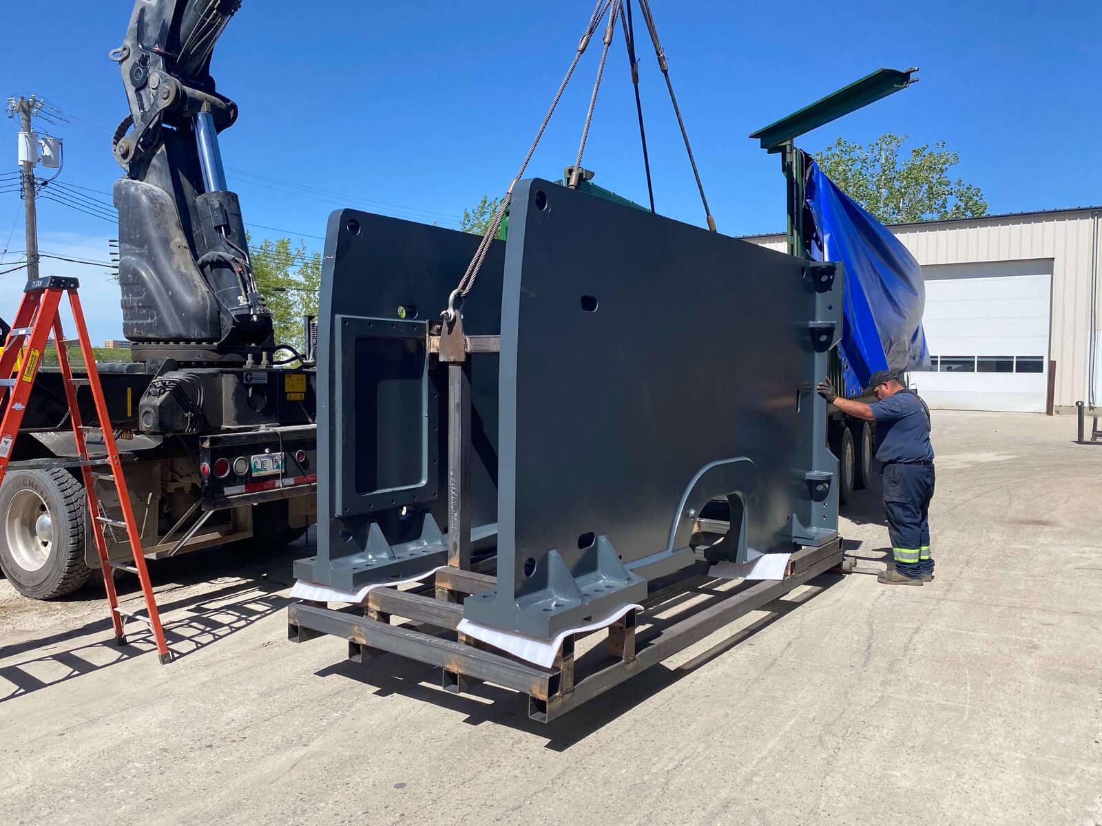
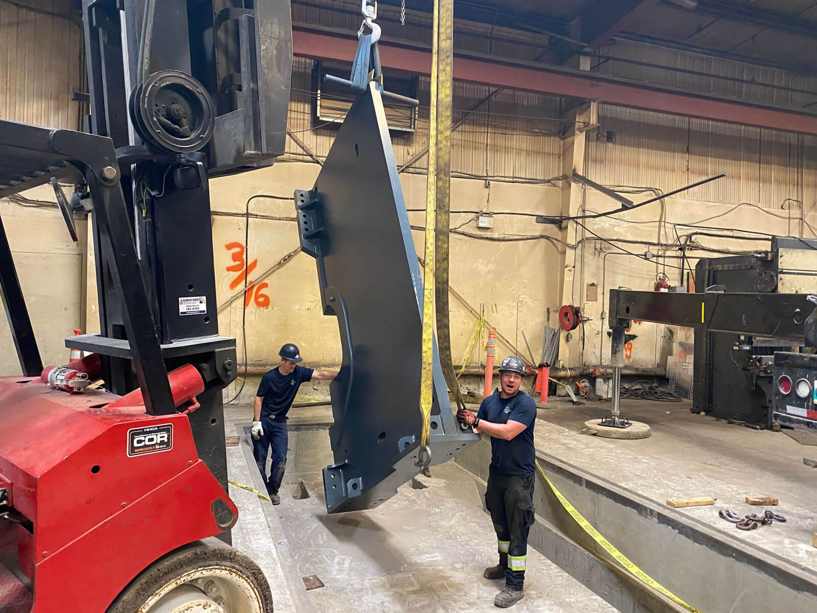
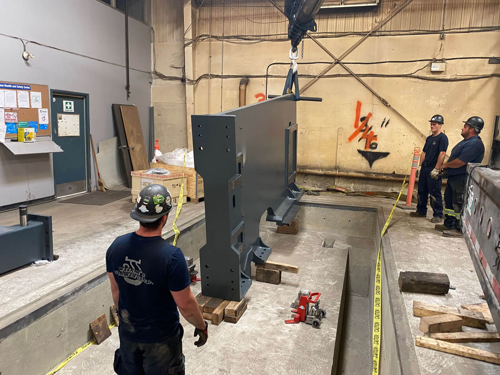
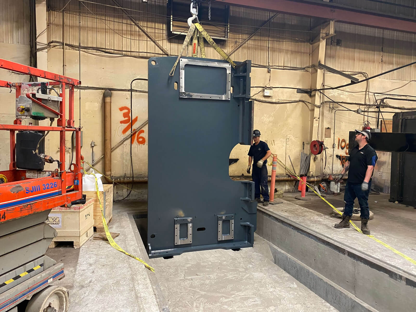
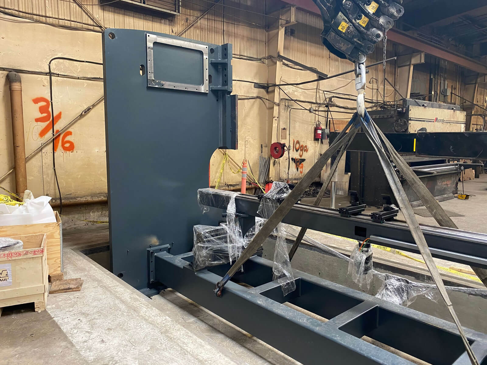
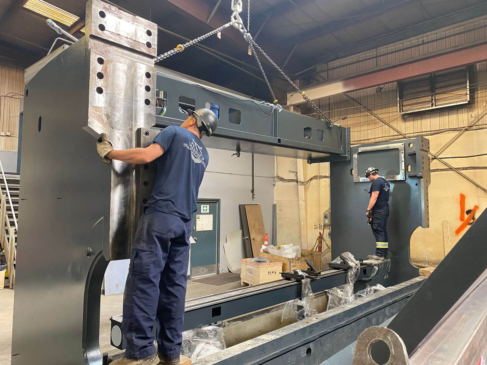
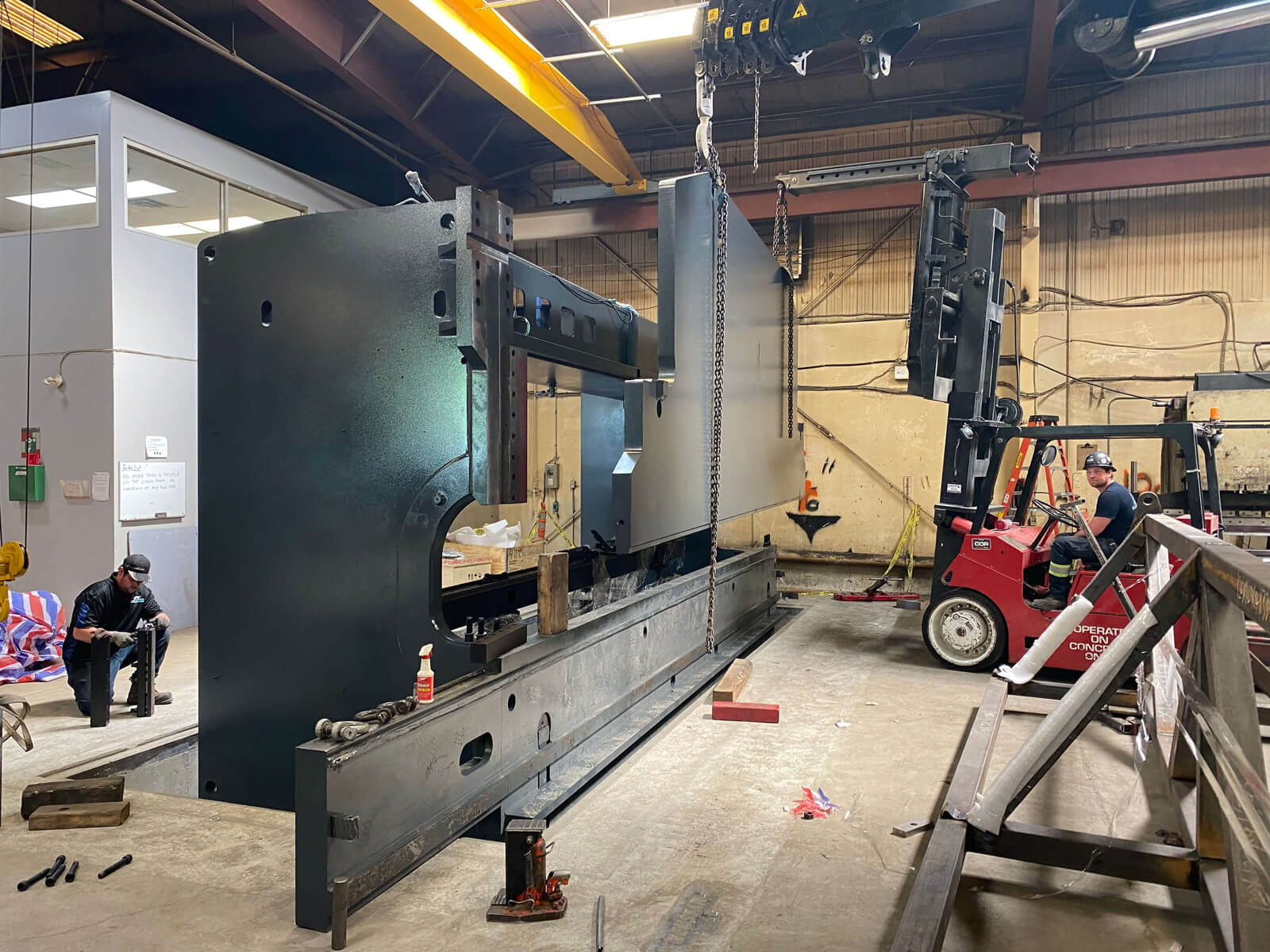
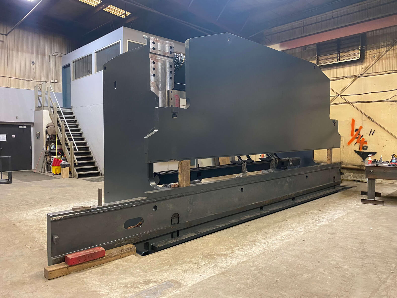
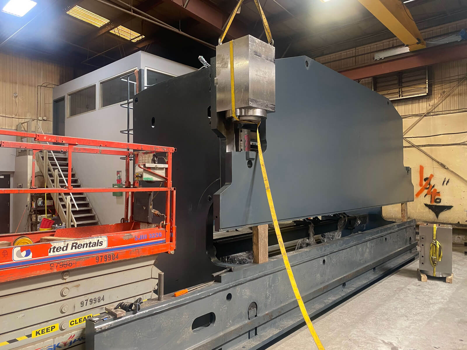
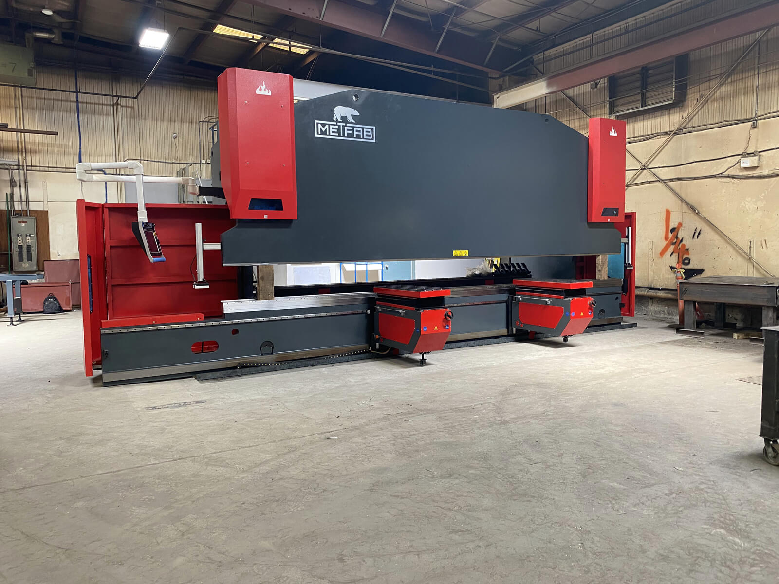
Step 2 – Frame Installation
The frame is separated into 4 parts: 2 side frames, the bottom ram and the top ram. These are the heaviest parts of the machine. The top ram alone weighs 27,000 lbs and it measures just over 24 feet by 8 feet high.
As for the foundation, it was prepared several weeks before the arrival of the machine according to the foundation plan that we sent to the customer.
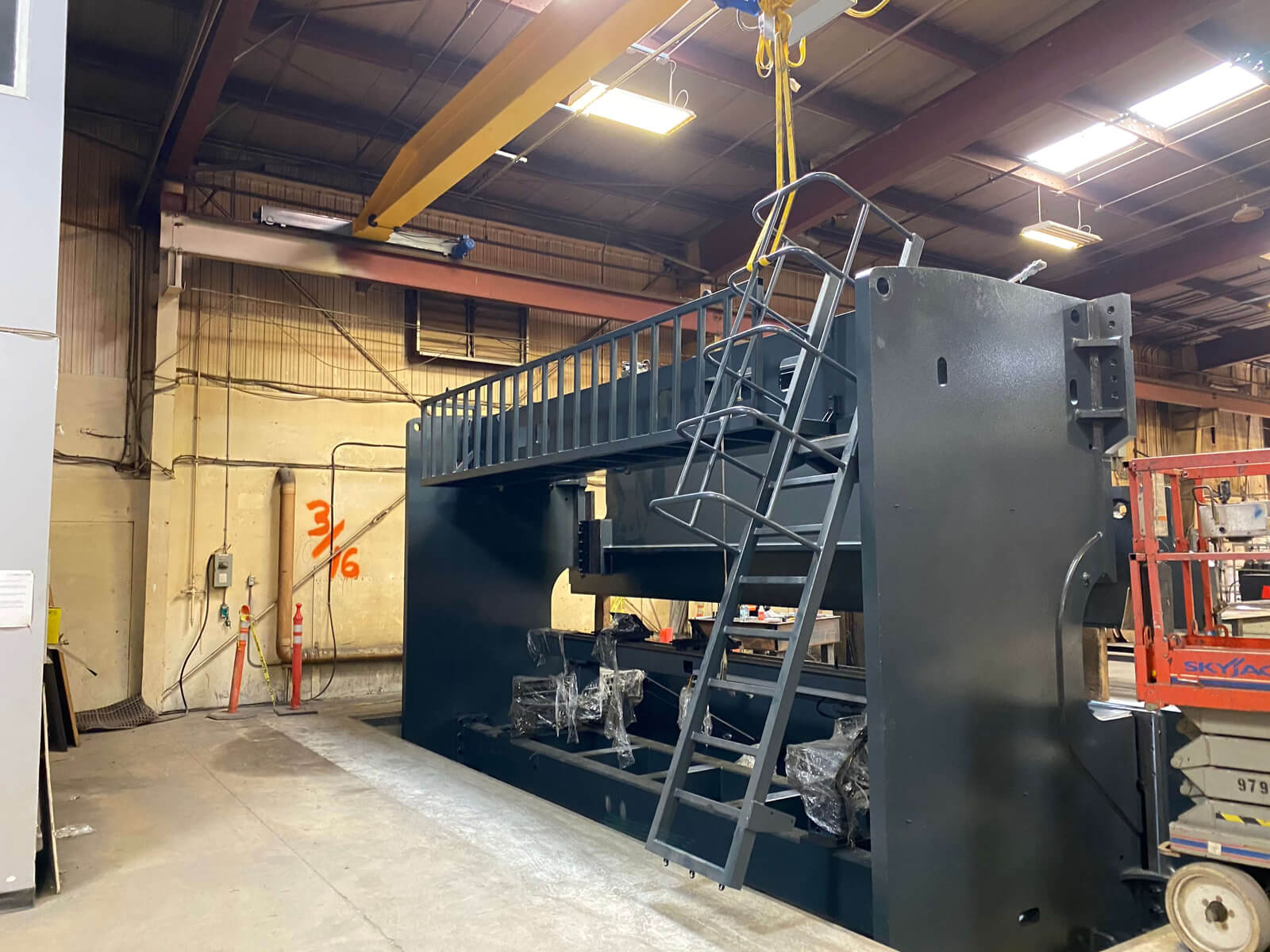
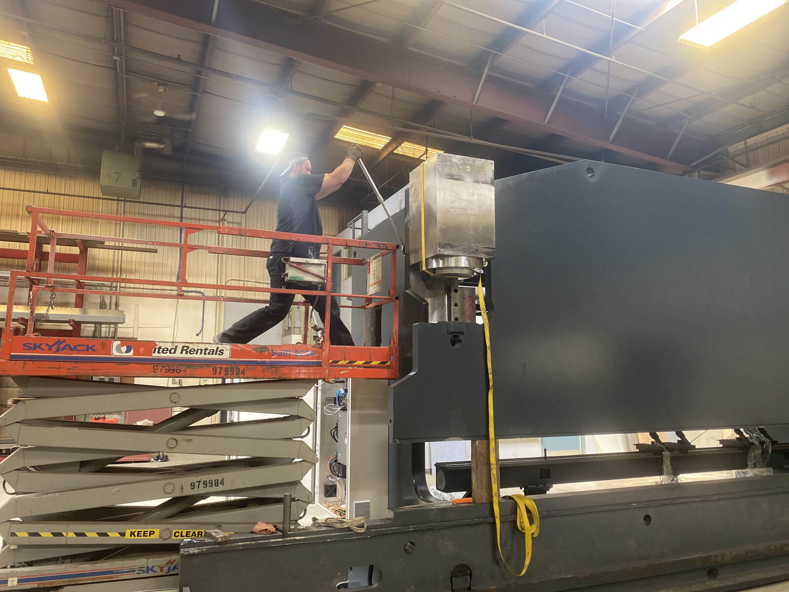
Step 3 – Hydraulic cylinders and maintenance platform
Once the frame is installed, we can mount the maintenance platform, which allows technicians to climb to the top of the machine for maintenance, and we can install the hydraulic cylinders.

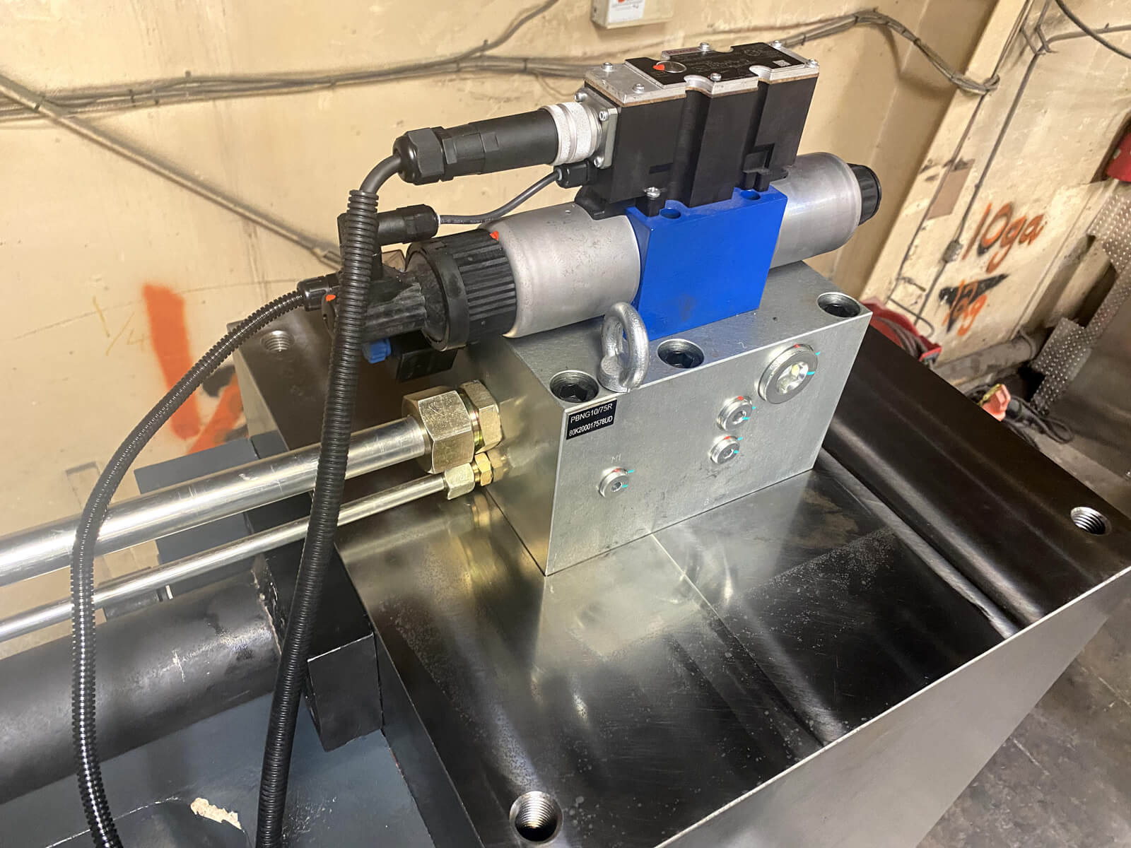
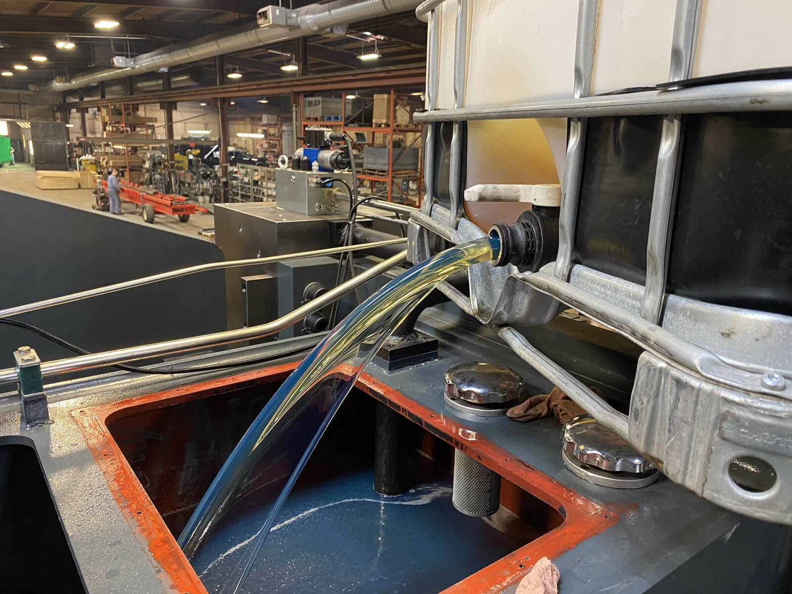
Step 4 – Engine installation and oil filling
We’re installing the engine at the top of the brake. We’re taking the opportunity to fill the oil tank with a capacity of more than 1200L.
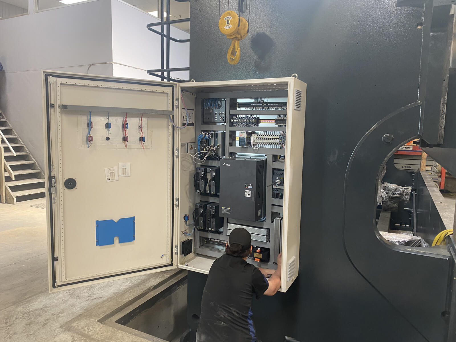
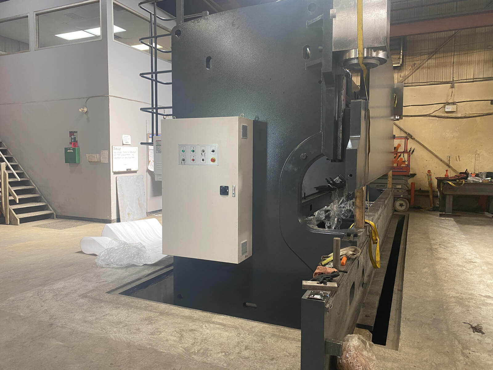
Step 5 – The electrical panel
If we want this massive press brake to work, we must install the electrical panel and make all the necessary connections.
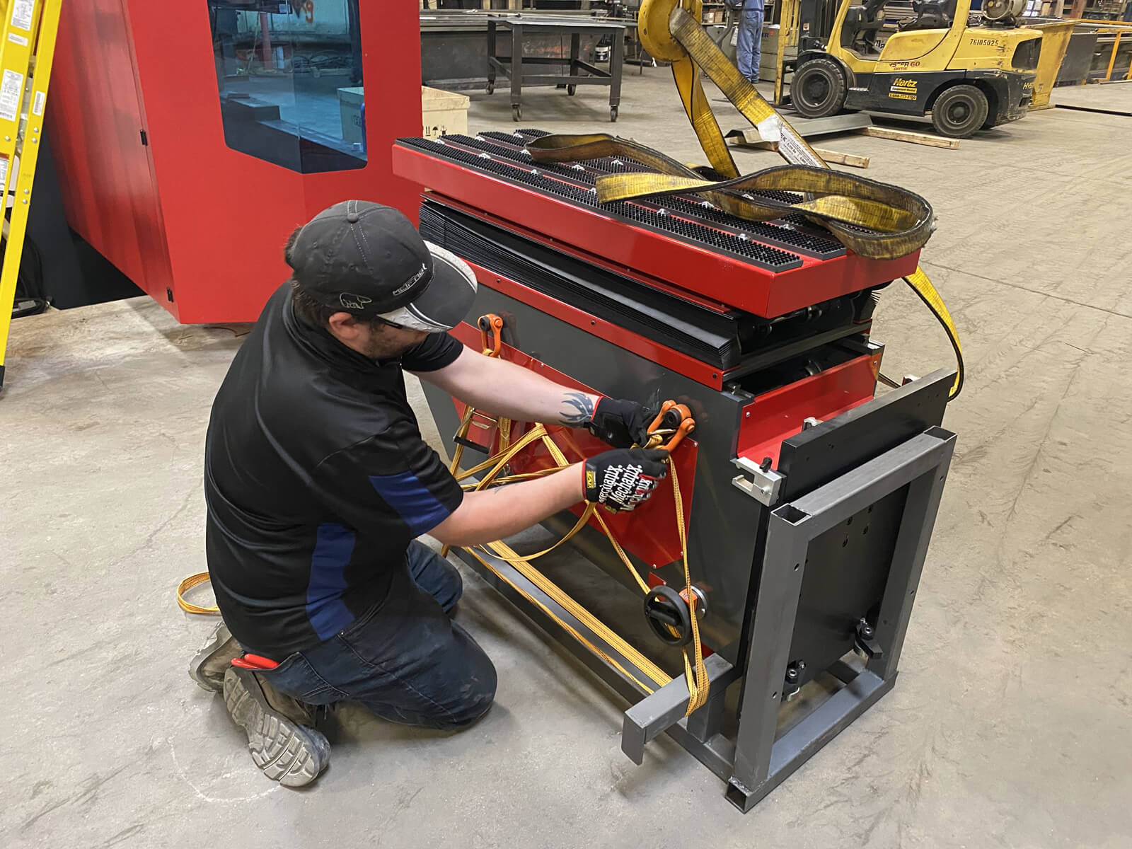
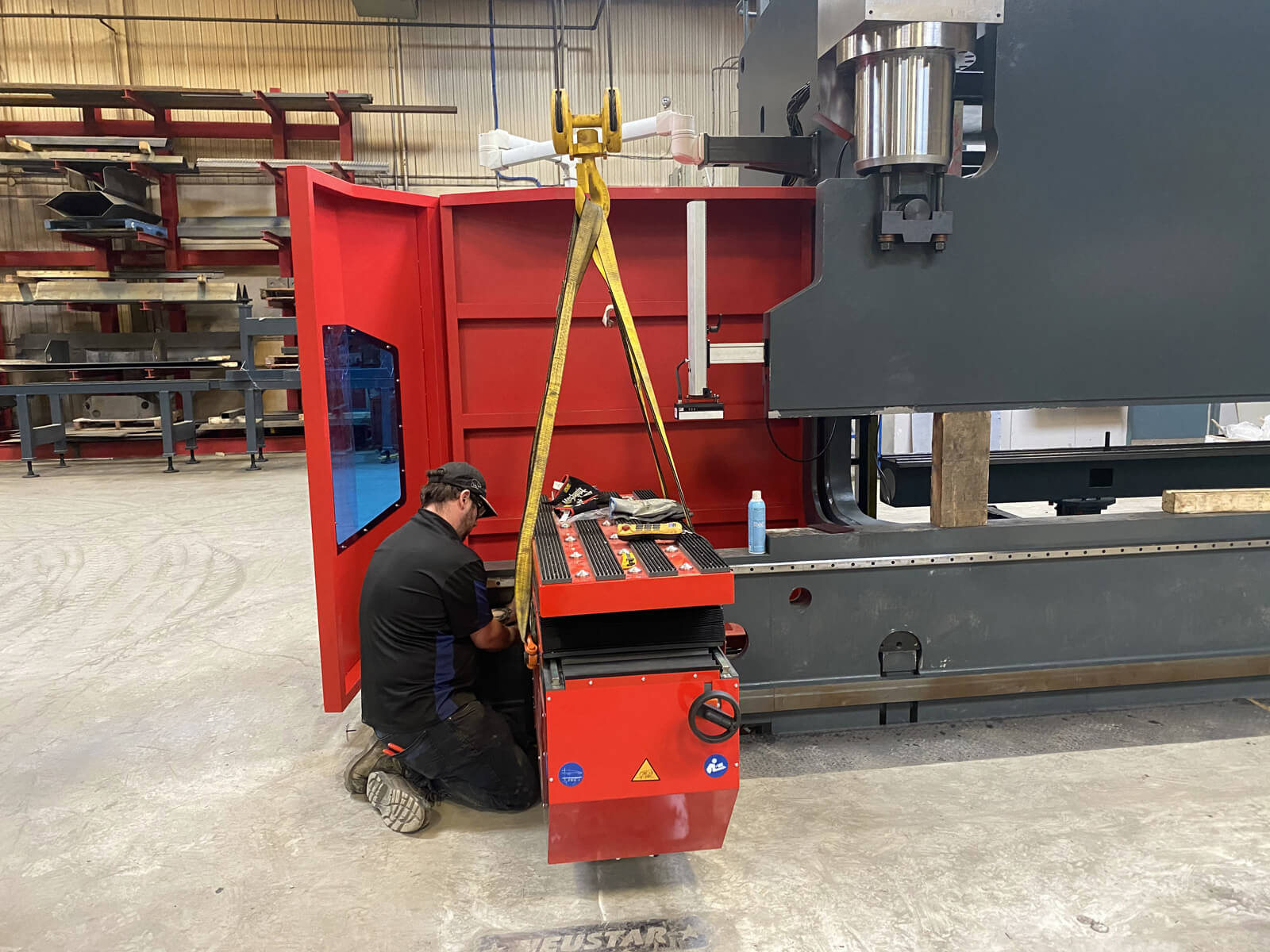
Step 6 – Installation of the automated sheet supports
For a press brake of this capacity, the automated sheet supports are necessary, they will automatically drive the sheet.
Watch the video of the the automated sheet supports
Step 7 – Backgauge
We’re testing the back gauge that’s controlled by the Delem 69t CNC


Step 8 – The finals
The finishing touches are: Installation of the backlit guards and the drilling for the pneumatic clamping.


All that remains is to install the tools and train the operators.


